top of page


Conceptual Aircraft Design and MDO
Introduction: At the Present day scenario the development of new aircraft either it is military or civil aircraft is more complex and competitive due to customers need for high performance and economical product. To design such complex machine within short time frame needs very advance numerical tools for rapid different design iterations.
The main aim of the research work to come up with a simple but robust and sophisticated numerical tool for conceptual aircraft design. To achieve this task knowledge based approach in aircraft design is adopted with the aid of multi disciplinary design optimization technique.
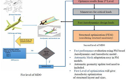
The design and optimization is decided into two levels .1) The using the customer input need and using the previous knowledge gain and base design is created. The aerodynamics performance of the base design is assessed using 3D PM tool which is computationally very fast compare to CFD. 2) Once the aerodynamics characteristics are achived the Aeroelastic performance of the aircraft is assessed using reduced order model(ROM) Aero-elastic tool. The complete strategy of two level design and optimization is presented in the figure(left) and an aerodynamics model inthe figure below. The Aero-elastic tool is developed using Non linear beam model+3D PM with lose coupling.
Fig: Aerodynamics simulation of civil aircraft using 3D PM
Fig: Two level conceptual aircraft design and Optimization Strategy
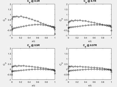
Aeroelastic coupling: The ROM based aeroelastic tool is used for analyzing the aeroelastic performance of the entire aircraft model in the 2nd Level optimization part. The entire aircraft is modeled using non linear beams with multiple DOF and the aerodynamics loads are estimated using 3D panel method. In the figure below a example of flexible wing is presented where the static deflection and the oscillation of the wing at 150 m/s wind speed is presented with unsteady wake shape. The pressure distribution on the undeformed shape is presented in the bottom right corner figure.

Introduction: The main of the research work is to hydrodynamics modeling of ship propeller to estimate the pressure distribution over the blade surface and also to estimate the other parameters e.g thrust coefficient (Tk). Later the pressure distribution will be used to analyses the cavitation phenomena.
For the modeling purpose DTMB 4119 propeller is modeled using 3D unsteady PM and free wake shape for J=0.833 is presented in the video above. The pressure coefficient distribution (Cp) at different sapnwise position of J=0.833 is presented in the figure below where as experimental validation of TK vs J is presented in the top right figure. The results has good agreement with exp data.
Fig: DTMB4119 Propeller wake shape using 3D PM @J=0.833
Fig: Thrust coefficient Vs advance ratio (J)
Application of 3D Panel Method in Ship Propeller design
bottom of page